Introduction
In recent past, GPR has become a go-to technology for scanning and locating undeground utilities. The utilization of Ground Penetrating Radar survey technique was utilized for detailed investigation and analysis of the utilities within Aga Khan Mzizima Secondary School, Dar es Salaam Tanzania. In the realm of modern domains of engineering, design, infrastructure development and expansion, it is prudent for accurate and comprehensive surveying techniques. Organizations, Government departments, and institutions seek to periodically develop new facilities, expand existing infrastructure or establish new utilities, therefore the need for acquisition of reliable data to inform decision-making processes cannot be overstated.
Ground Penetrating Radar (GPR) is one of the invaluable tools to achieve this endeavor because it offers a non-destructive and efficient means of subsurface investigation. GPR, a geophysical method that employs electromagnetic radiation to image the subsurface when integrated with other survey methods such as topographical survey and hydrological investigations indeed bring forth a rich pool of data for consideration to enable facility managers, engineers, and planners obtain detailed insights into the composition and structure of the ground beneath the sites.
Project background
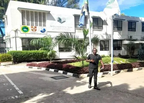 Aga Khan Mzizima Secondary School is an educational institution located in Dar es Salaam, Tanzania. The institution is one of the many institutions under the umbrella organization called Aga Khan Education Service-Tanzania (AKES-T); which is associated with the Aga Khan Development Network (AKDN). Aga Khan Mzizima Secondary School prides itself in providing quality education through the national curriculum; while incorporating the philosophy of the Aga Khan Development Network (AKDN), which put emphasis on diversity, ethics, and community service. It’s known for academic brilliance, extracurricular activities, and all-inclusive approach to education.
In the spirit of continuing with this noble service, the institution sought to do infrastructural overhaul and expansion works. This therefore calls for thorough investigation and design of the proposed sites. Ground Penetrating Radar (GPR) Survey identifies as one of the technological techniques to give solutions to the proposed mapping and investigation of the subsurface utility lines within the facility. The GPR survey was therefore considered to identify and give a clear insight into the underground utilities in order to aid in design and construction activities.
Topography
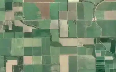
Generally, topography of a given area refers to the general physical features of the site such as elevation, slope, and natural formations such as rivers, valleys and mountains. Topography is often depicted by topographical maps which illustrate elevation with the use of contour lines and are complemented with planimetric maps that represent features such as buildings, roads, trees, and infrastructural establishments of an area. And for the purpose of this survey, the topography of the area was found to be generally flat with an elevation difference of 3.4739M over an area of 22,900 m².
Scope and project objectives
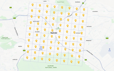
 The main scope of this project was to collect data by the use of surveying equipment in order to give output as spelled out in the scope of work. The project site is located at Aga Khan Mzizima Secondary School, Dar es Salaam Tanzania located at: (9246937.07S ,530751.69E) of which the area of approximately 22,900 m² out of which 17,777.94m² was surveyed using GPR technology. The objectives of the project were as follows:
- To help in supporting the consulting services for the refurbishment of detailed design and construction of the Aga Khan Mzizima Secondary School project based in Dar es Salaam, Tanzania.
- To identify the underground utilities through scanning the site by the use of GPR to allow visualize the buried objects, structures and geological features.
- Provide a detailed CAD drawing as well as 3D model showing all the scanned utilities that appear within the extents of the area.
- Provide the client with a comprehensive survey report with key findings and recommendations on mapped underground utilities.
GPR methodology
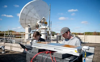
Ground Penetrating Radar survey is a non-destructive geophysical method that produces a continuous cross-sectional profile or record of subsurface features, without drilling, probing, or digging. A GPR operates by transmitting pulses of ultra-high frequency radio waves (microwave electromagnetic energy) down into the ground through a transducer (also called an antenna). The transmitted energy is then reflected from various buried objects or distinct contacts between different earth materials. The GPR antenna then receives the reflected waves and stores them in the digital control unit. USRADAR GPR model Q5 Series, was used for the survey along with 500 MHz paired antenna for scanning down to depth of 10m. We carried out our scanning by using GPR then we positioned the utilities using the RTK/GNSS.
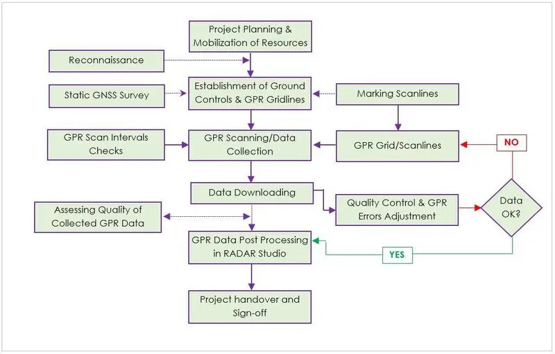
The purpose of this survey was to thoroughly capture data with regard to subsurface utilities using Ground Penetrating Radar technology and utility detection technologies that will aid in the comprehensive analysis in understanding the positions, orientation and depth of the features for informed decision making for the success of insightful design, construction and implementation of the proposed facility improvement and or development. GPR data collection process began by preliminary scanning to ensure that the survey parameters were okay. This is then followed by the actual survey. The scans are done across (cross-sectional) and along (longitudinal) the area being scanned using one axis starting from same baseline and later on the perpendicular axis starting on baseline of the starting point. This allows the collection of data for utilities running across and those located along the scan zone as shown by the radargrams below.
By adopting this advanced underground survey technology i.e. incorporating the Ground Penetrating Radar and Electro-Magnetic Locators (EML), we analysed the reflected signals from structures, services, buried objects and layers beneath the ground. With statutory record plans, visual inspections of all lifted service cover on site – we created an accurate plan of the subsurface environment in multiple formats including 3D. A Utility Mapping Survey will provide the client with the confidence to progress with the project and ensure there are ‘no-surprises’. Furthermore, adhering to all health and safety regulations ensured that all survey best practices were employed.
Hardware and Software
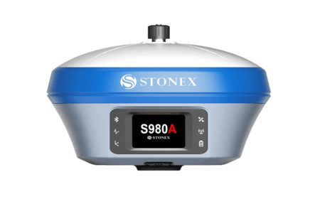
(i) Stonex S800A GNSS
(Global Navigation Satellite System) GNSS equipment: The Stonex S800A is a precise GNSS receiver that provides accurate positioning data. It was used to occupy existing control points and georeference the GPR data for precise mapping. The following are some of its specifications:
 GNSS signals Received: It connects with some of the channels like GPSL1, L2, and L5. GLONASS L1, BeiDou and Galileo.
- Channels: It contains 394 multi-constellation channels.
- Positioning Accuracy: It has Real-time kinematic of horizontal 8mm + 1ppm, vertical 15mm+ 1ppm,while post-processed is at 3mm+0.5ppm horizontal and 5mm+0.5ppm vertical
- Communication: It communicates with both the WIFI and Bluetooth.
- Data Storage: During field work it stores its data automatically into its internal storage which will later be beamed for processing.
- Software compatibility: The logger device is installed with windows operating system that is compatible with “Field Genius” software that enables Bluetooth connection and configuration of receiver modules.
- Antenna: It’s integrated with an antenna that supports radio connection between the two receivers.
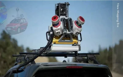
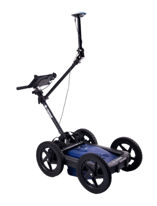
(ii) Ground Penetrating Radar (GPR)
USRadar Q5 GPR is a high-performance GPR system designed for subsurface imaging. It offers a wide frequency range and adjustable antenna configurations for various surface material types. The Q5 GPR is capable of detecting and imaging underground objects and voids making it ideal for subsurface utility mapping. The Specifications of a GPR system can vary depending on the manufacturer and the specific model, here are some of the common specification of USRadar Q5 GPR that was employed for the purpose of this survey:
- Frequency: it operates at various frequencies that range from a few Megahertz (MHz) to several Gigahertz (GHz).
- Pulse Repetition: the rate at which pulses need to be transmitted into the ground, a higher PRF allows faster data acquisition but may reduce the depth of penetration
- Transmitter Power: this depends on the strength of the radar signal. Higher power systems can penetrate deeper into the subsurface but this requires more energy and they can generate more noise hence more disturbance.
- Depth of Penetration: this indicates how deep the radar can transmit its waves into the ground, and also depends on the frequency and power of the system.
- Resolution: GPR offers different levels of spatial resolution which determines how finely subsurface can be imaged.
- Display and Data Output: GPR has software for data visualization and analysis which provides real-time displays of GPR and allow for data export in various formats for further analysis such as GPR Slice software commonly used for most GPR devices.
- Battery Life: the life of a battery of a GPR is very crucial and longer battery life allows for extended data collection.
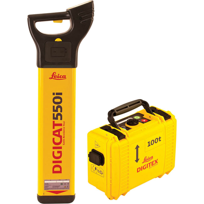
(iii) Leica Ezi-CAT 200 Cable Locator
This device is designed to work in conjunction with the EziTRACE signal generator that operates with a constant signal output of different frequency of either (8 or 33 kHz). The Ezi-CAT 200 Cable Locator; power mode which is a default mode, Radio mode, 8 and 33 kHz.
The different frequency ranges detect the underground utilities through impressing a distinct signal onto the service to be traced easily from above the ground. Some of the Ezi-CAT 200 Cable Locator features include:
 Frequency Range: It has different frequencies that aid in detection of various types of utilities like power cables and telecommunication cables.
- Signal strength Indication: There are different signal strength of 8 and 33 Khz that help the user in precise identification of the utilities.
- Audio and visual Indicators: The cable locator makes different sounds that help the user to perceive the presence of buried anomalies.
- Battery Life: This depends on the intensity of device operation by the operator on a single set of detected utilities.
- Water and Dust Resistance: This helps the cable locator from different level of protection against any environmental factors that might make it not to function.
Data processing and analysis
GPR being a non-invasive technique that uses radar pulses to image the subsurface of the earth. GPR data was processed to create sub-surface images and identify potential underground utilities. Through the use of GPR Slice Software which is a two dimensional image or cross-sectional view of the sub-surfaces obtained.
i) Accuracy Analysis: Quantification of the errors like limitations in terms of resolution which can vary based on factors such as antenna frequency and ground conditions that are associated with the GPR data by comparing with known features, also there was evaluation of the spatial and depth resolution of the GPR data. However false and negative rates were calculated to assess the reliability of feature identification. For the Global Navigation Satellite System GNSS, the Equipment was set at a known control point MAG 01 and checked against the other four (4) control points where the accuracy was found to be within the agreeable threshold of + 0.002m.
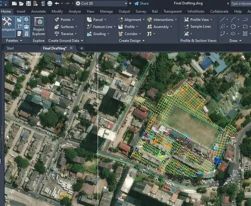 ii) Software Used: For data visualization, specialized software like ArcMap, AutoCAD CIVIL3D and GPR-slice were used to process the raw GPR data by applying data processing algorithms and workflows that gave expected output as outlined in the scope of work. Data interpretation was done through identifying and marking the reflections of features in the GPR data. However, post- processing was done through depth conversion by the use of estimated propagation velocity; visualization of the subsurface features was done to create 2D images.
iii) Data Visualization: This was done by the use of Time-slice maps that display the GPR data at specific depths with different colors representing the variation of signal amplitudes that indicates the subsurface features. Also the depth slices that help in the provision of cross-sectionals that help in viewing the sub surfaces at different depths; this is useful when identifying horizontal features.
1. Water pipes
They were of different materials like PVC, and galvanized with different diameter typically ranging from 0.5 inches and up to 4 inches. Their depths vary from over the surface to depths of 0.45 meters below the ground surface. Most of the main water pipes originate from the underground main water tank towards the strategic pumping points from where the secondary pipes supply the various taps and water points whereas the drinking water lines originate from the Reverse osmosis treatment and filtration point.
2. Sewer lines
They are made of concrete which had a varying diameter from 4 inches for lateral lines to 6 inches or more for major trunk lines; they were typically buried at depths ranging from 0.4 to 0.6 meters depending on the soil conditions and terrain of the area.
3. Low voltage Electric cables
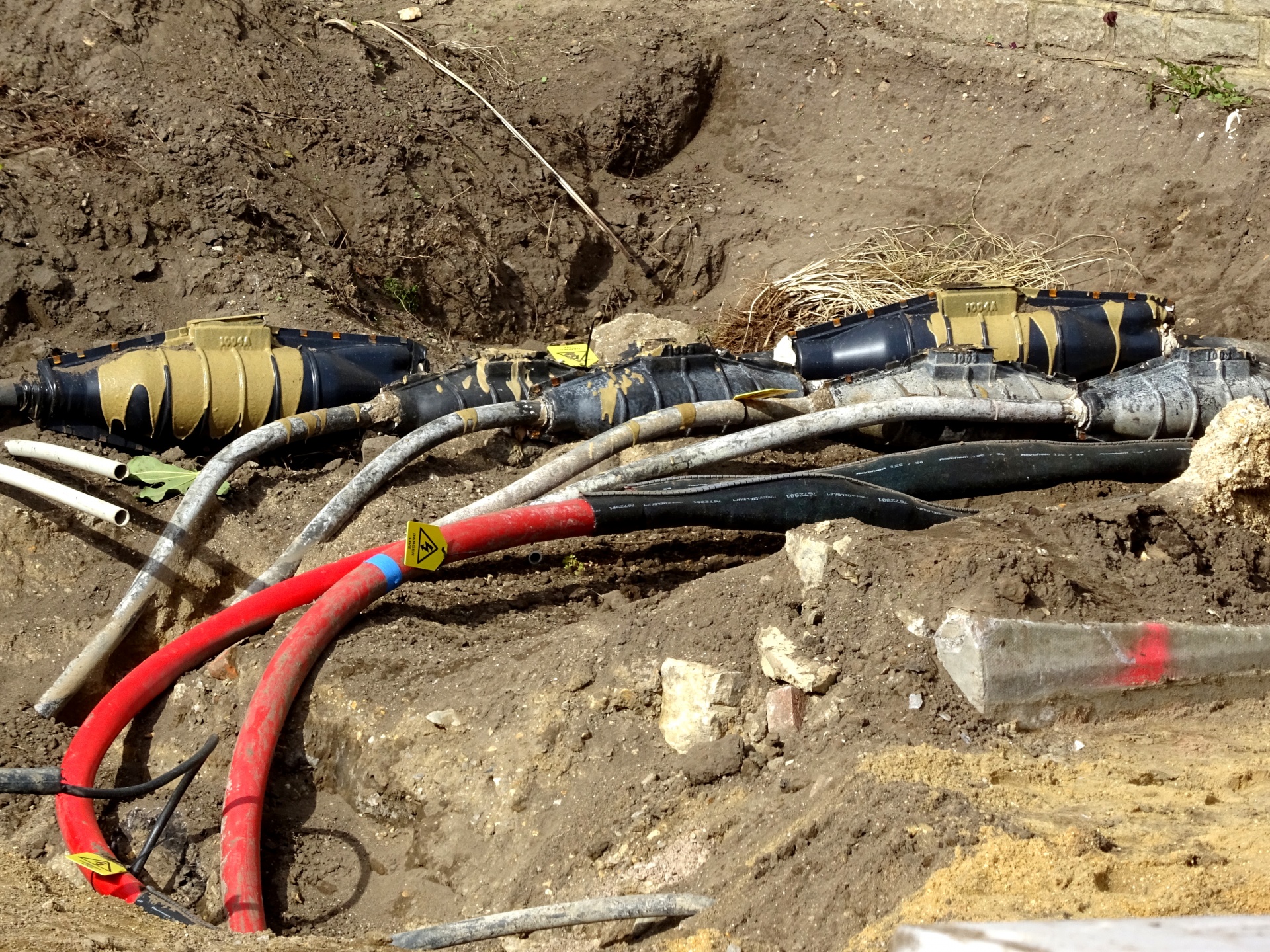 Low voltage electrical lines commonly initialized as (LV) lines are power lines that carry electricity at relatively low voltages compared to the high voltage (HV or HT). LV lines are used to distribute electricity from sub-stations (transformers) to homes, businesses and other infrastructure. The lines can either be overhead or underground where the mains supply line from a substation just outside the institution supplied overhead cables via poles to a facility meter on Kilimanjaro Block and finally to a distribution unit within the same building. From the distribution unit, most of the electric lines run underground to different blocks. There is also the supply line from the generator that runs underground from the generator unit to the central distribution unit. The depths begin from above the ground to 0.43m below the ground.
4. Communication cables
Communication cables are of various types depending on their specific purpose, they come in different materials such as coaxial cables, twisted pair cables such as Ethernet cables, fiber optic cables that are used to transmit data, signals or electrical power between devices or locations. Most of the cables were noted to be embedded inside PVC pipes of different diameter depending on the number of strands. Identification was majorly based on visibility at entry and exit point or at inspection/junction chambers.
5. Closed Circuit Television (CCTV) cables
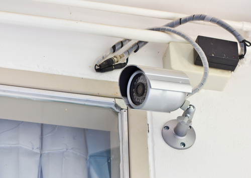 CCTV is a system in which video cameras transmit signals to a specific set of monitors in central control rooms to allow surveillance and security monitoring of a specific area commonly in institutions, homes and public places. Aga Khan Mzizima Secondary School has a series of security monitoring CCTV system to ensure safety and security procedures are adhered to. From the GPR survey it was noted that some of the CCTV system cabling runs within the subsurface to connect the cameras installed at different strategic points.
6. Septic tanks, Manholes and Soak pits
Septic tanks are underground wastewater treatment structures commonly used in areas not connected to centralized sewer systems. They are covered with heavy duty plastic covers or metallic covers. The household sewage and wastewater are collected from sinks, toilets, showers and laundry areas via underground pipes. The collected water is treated and separated inside the septic thanks with the use of bacteria which breaks down solids and partially treating the wastewater. The liquid effluent that results from the treatment process is directed to soak pits commonly known as drain fields where it percolates into the soil.
Conclusion and recommendations
The application of GPR technology holds immense promise in enhancing the planning, design, and execution phases of institutional expansion projects. By facilitating the identification of subsurface anomalies and obstacles before construction commences, GPR surveys mitigate the risks of costly delays, unforeseen complications, and potential safety hazards. Moreover, by providing invaluable data on soil conditions, geological formations, and buried infrastructure, GPR surveys empower decision-makers to optimize site utilization, minimize environmental impact, and ensure the long-term viability and sustainability of their developments.
The GPR survey conducted at Aga Khan Mzizima Secondary school, Tanzania using the USRadar Q9 GPR and Stonex S800A GNSS machine provided valuable insights into the subsurface conditions. The identification of underground utilities will be crucial for future construction, development and maintenance projects. The georeferenced data collected during this survey and integrated into AutoCAD Civil 3D to create accurate utility maps, will henceforth allow efficient project planning and risk mitigation. And indeed proper understanding of the depth and orientation of the underground utilities is very essential for effective planning, designing, maintenance and management of the institutions’ infrastructure.
Ad: Explore the world with Expedia

Flewflew: AI solutions provider in Africa

OrbiCollect: Mobile mapping made easier!

NSE Stock Market: Buy & Sell Shares